What is the Q value of an inductor
In the design, as long as the inductor is useful, the Q value of the inductor cannot be bypassed. But often many people do not understand, what is the Q value of an inductor? What effect does the Q value of the inductor have on the inductance and the circuit? Then we will talk about the meaning of the inductor Q value and the issues that should be paid attention to in the application process. Q value: also called the quality factor of inductance, it is the main parameter to measure the inductance device. It refers to the ratio of the inductance presented by the inductor to its equivalent loss resistance when it works under a certain frequency of AC voltage. The higher the Q value of an inductor, the smaller its loss and the higher its efficiency. The quality factor of the inductor and the DC resistance of the coil wire, the dielectric loss of the coil frame and the iron core. The requirements for the quality factor Q are different depending on the use occasion. For the inductive coil in the tuning loop, the Q value is required to be higher, because the higher the Q value, the smaller the loss of the loop, and the higher the efficiency of the loop; for the coupled coil, the Q value can be lower; and for low frequency or High-frequency chokes are not required. The improvement of the Q value is often limited by some factors, such as the DC resistance of the wire, the dielectric loss of the coil frame, the loss caused by the core and shield, and the skin effect during high-frequency operation. Therefore, the Q value of the coil cannot be made very high, usually the Q value is tens to one hundred, and the highest is only four to five hundred.
What are the functions of the Q value of the inductor?
If the Q value is too large, it will cause the inductor to burn out, the capacitor to breakdown, and the circuit to oscillate. When Q is very large, there will be the phenomenon of VL=VC》》V. In the power system, this phenomenon often leads to the breakdown of the insulation of the inductor and the dielectric in the capacitor, causing losses. Therefore, resonance should be avoided in the power system. However, in some radio equipment, resonance is often used to increase the amplitude of weak signals.
How to convert the Q value of the inductor?
The factor can be written as Q=2pi* energy stored in the circuit/energy consumed in one cycle of the circuit. The relationship between the passband BW and the resonant frequency w0 and the quality factor Q is: BW=wo/Q, which indicates that a large Q means a narrow passband, and a small Q means a bandwidth. Q value calculation formula: Q=wL/R=1/wRC where: Q is the quality factor w is the power frequency when the circuit is resonant, L is the inductance, R is the resistance of the string, C is the capacitor, and the Q value is the quality factor, which is useful work Compared with total work.
Factors affecting the Q value of the inductor
The quality factor of an inductor is related to the DC resistance of the coil wire, the dielectric loss of the coil frame, and the loss caused by the core and shield. Some people deliberately lower the Q value of the inductor in order to avoid high-frequency resonance/gain. The way to reduce the Q value can be to increase the resistance of the winding or use a magnetic core with larger power consumption. The Q value is generally referred to as the quality factor, which is a dimensionless unit that measures the performance of a component or resonant circuit. Simply put, it is the ratio of the loss in the ideal component to the component. This element can be an inductor, a capacitor, a dielectric resonator, a surface acoustic wave resonator, a crystal resonator, or an LC resonator. The value of Q depends on the actual application, not the bigger the better. For example, if you design a wideband filter, an excessively high Q value will deteriorate in-band flatness if no other measures are taken. When using LC decoupling applications in power supply decoupling circuits, high-Q inductors and capacitors are prone to self-resonance, which is not conducive to eliminating interference noise in the power supply. Conversely, for the oscillator, we hope to have a higher Q value. The higher the Q value, the more beneficial the frequency stability and phase noise of the oscillator. Different applications have different requirements for Q values. The quality factor of the component, that is, the size of the Q value, depends on the production process, production materials and application environment of the component. For example, for the same inductor, if other parameters remain unchanged, only the thickness of the winding inductor wire is changed, the inductance Q value of the thick wire is higher than that of the thin wire. If the wire is plated with silver again, the inductance of the silver-plated wire will have a higher Q value than the inductance of the non-silvered wire. As for the Q value of the dielectric resonator, it depends on the material and manufacturing process of the dielectric resonator. The size of the Q value is also related to the operating frequency. The general inductance will increase its Q value as the frequency increases. But it has a limit. When the Q value of the inductance drops abruptly after the limit frequency point is exceeded, the inductance loses its function as an inductance. At this point, dielectric resonators, surface acoustic wave resonators and crystal resonators are more obvious. When the working frequency deviates from their resonance frequency, their Q value will drop sharply, and they will not work. The quality factor describes the ratio of the energy storage of the loop to its energy consumption per week. Because the product of the same frequency band and the quality factor is the resonant frequency of the loop. Therefore, when the resonance point is guaranteed, the quality factor and the width of the passband are a pair of contradictions. Therefore, it cannot be said that the higher the quality factor, the better, but the higher the Q value required for the frequency band, the narrower the passband of the resonance, which means that the frequency range included is narrower. If a wider passband is required, the Q value The smaller the better. In the frequency selection circuit (select a certain frequency), the wave blocking circuit (stop a certain frequency), the absorption circuit (attenuate a certain frequency), and the trap circuit (remove a certain frequency), a certain frequency f is used or removed. At this time, the larger the Q value, the better. This is to use the frequency f of the resonant circuit at resonance. When the LC parallel resonant circuit resonates, the circuit impedance is the largest, which is equivalent to an open circuit, so that the frequency signal with the frequency f cannot pass, so as to prevent this The purpose of the signal. When the LC series resonant circuit resonates, the impedance is the smallest, which is equivalent to a short circuit. At this time, the frequency of frequency f can easily pass, and other signal frequencies are blocked, and the purpose of frequency selection can be achieved. Regarding the relationship between the magnetic loss and the Q value of the magnetic ring inductance, the power supply design requirements are becoming more and more stringent, which requires us to carefully analyze and calculate each problem point. The calculation of the magnetic loss is generally based on the volume and correlation of the magnetic core. The loss curve is simply calculated, but it appears in actual work that the different winding methods of the same magnetic core and the same winding method of the same magnetic core have different tightness, but they bring different temperature rise gaps.
Types and characteristics of RF (high frequency/radio frequency) inductors
gist
Small RF inductors are used in RF circuits based on mobile phones. Small RF inductors can be divided into three types of inductors according to different process methods. Different inductor types have different characteristics. This time, the characteristics and selection points of inductors will be introduced.
Types and characteristics of RF inductors
According to different process methods, RF inductors can be divided into three types: winding, multilayer, and thin film. The external photos are shown below.
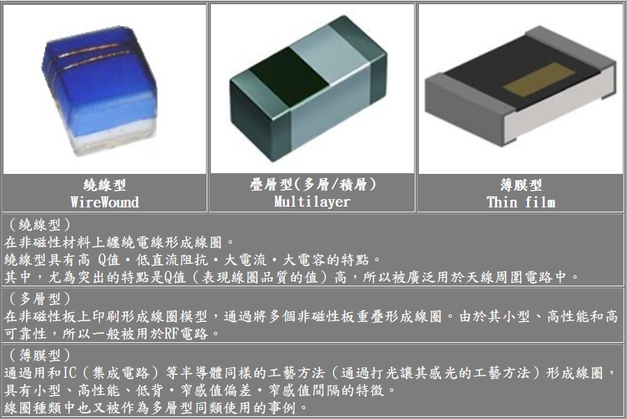
The following table shows the characteristics and use circuits of different types of RF inductors
| Types of | feature | Use circuit |
| Winding | High Q value, low DC impedance, large current, large inductance | Around the antenna |
| Multilayer | Small size, high performance and high reliability | General RF circuit |
| film | Small size, high performance, low back , inductance tolerance, narrow inductance interval, high Q value | RF impedance synthesis circuit around the antenna |
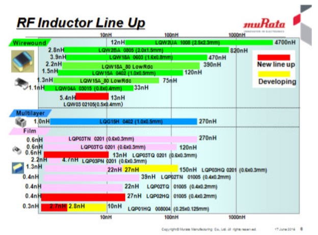
RF inductor lineup
The picture below shows the comparison of Murata’s RF inductor lineup with Japan.
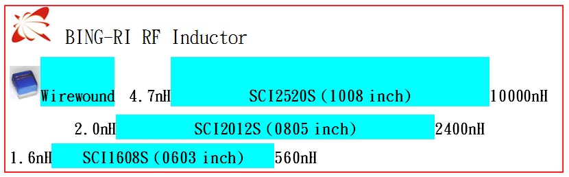
The RF inductors produced by Parallel have been continuously developing from 12min to 60min for the Q value (quality factor).
Conclusion
Small RF inductors are widely used in RF circuits based on mobile phones. Therefore, it is necessary to select appropriate components according to the circuit and Q-value characteristics. With the current trend of high-speed radio frequency transmission, it is used in electronic products such as Bluetooth headsets, mobile phones… It is an indispensable original.